How to Choose the Right Inside Heat Exchanger?
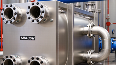
Choosing the right Inside Heat Exchanger begins with the process, not the product catalogue. Every system has different demands. Fluid temperature, pressure, flow rate, fouling risk, and available space must be examined together. A unit that performs well in a clean laboratory may struggle beside a dusty furnace or a salt-laden cooling loop.
Dr. Sadik Kakaç, a respected heat-transfer researcher, wrote, “The design of heat exchangers is an art as well as a science.” This principle remains practical. Engineers must balance thermal performance, pressure drop, maintenance access, material compatibility, and total lifecycle cost. Plate models may offer compact efficiency. Shell-and-tube designs may provide stronger serviceability. Finned units can help when air is the working medium, but they demand careful attention to dust and corrosion.
Small details matter. A narrow service door can turn routine cleaning into a costly shutdown. A slight increase in fouling can reduce heat transfer and raise pumping energy. These outcomes are easy to underestimate.
Do not choose by size alone.
This guide explains how to compare Inside Heat Exchanger designs with clearer technical judgment. It considers real operating conditions, not only brochure ratings. It also questions assumptions that often survive because “the system has always worked.” That reasoning is convenient, but incomplete. Reliable selection requires accurate measurements, realistic safety margins, and advice from qualified engineers familiar with the application. When data is missing, the safest choice may be to pause, inspect, and measure again.
Define Heat Duty, Flow Rates, and Design Temperatures Before Selection
How to Choose the Right Inside Heat Exchanger?
Define the heat duty before comparing exchanger sizes. Heat duty is the energy the exchanger must transfer per unit of time. Calculate it from the process flow, specific heat, and required temperature change. Use actual operating conditions, not only design assumptions. A liquid entering at 80°C and leaving at 45°C needs a different exchanger from one leaving at 55°C. Numbers come first.
Flow rates strongly affect velocity, pressure drop, and heat transfer performance. Record the minimum, normal, and maximum flow for both sides. A unit sized only for normal flow may struggle during peak production. Check fluid viscosity at operating temperature, especially during startup. I have seen early designs underestimate cold-fluid resistance. That mistake can make a suitable exchanger look inefficient.
Set the inlet and outlet temperatures clearly, then calculate the available temperature difference. Consider fouling, seasonal cooling water changes, and possible flow imbalance. A small safety margin is useful, but excessive oversizing can reduce velocity and encourage deposits. Confirm allowable pressure, materials, connection sizes, and cleaning access with the process engineer. My own first selection would now include a fouling review earlier. It saves redesign time. Be careful with optimistic data. A measured flow rate is usually more reliable than a spreadsheet estimate.
How to Choose the Right Inside Heat Exchanger?
Define heat duty, flow rate, and design temperatures before selecting the exchanger. The comparison below uses water with a specific heat capacity of 4.18 kJ/kg·K; heat duty is calculated as Q = ṁ × Cp × ΔT.
Select an exchanger that can handle the required heat duty at the design flow rate and temperature range, while allowing sufficient margin for fouling, pressure drop, and operating variation.
Compare U-Values: 500–1,500 W/m²·K for Liquid-to-Liquid Service
How to Choose the Right Inside Heat Exchanger?
For liquid-to-liquid service, compare the overall U-value before comparing exchanger size. A practical range is 500–1,500 W/m²·K. Lower values often suit viscous fluids, fouling liquids, or modest flow speeds. Higher values usually require cleaner fluids, stronger turbulence, and tighter control of pressure drop.
At 500 W/m²·K, a hot-water loop heating thick oil may need more surface area. The larger exchanger can still provide stable outlet temperatures. At 1,500 W/m²·K, a compact unit may handle clean water circuits efficiently. High U is not free. Pumping power, vibration, erosion, and maintenance demands can increase.
U-value depends on both fluids, wall conductivity, flow arrangement, and fouling resistance. Never accept a catalogue value without checking operating conditions. Ask for the calculated coefficient at your actual inlet temperatures and flow rates. A laboratory estimate may look impressive, yet field performance can fall sharply after months of deposits.
A simple review should compare heat duty, logarithmic temperature difference, surface area, and allowable pressure loss. Check the cold-start condition too. It may control the design more than normal operation. I have seen undersized units meet the average duty but fail during winter startup. That mistake is easy to miss. Reconsider the estimate when fluid properties change with temperature. Thin fluids can become surprisingly difficult at low flow.
Target a 3–8°C Temperature Approach and Calculate LMTD
How to Choose the Right Inside Heat Exchanger?
Selecting an inside heat exchanger starts with the temperature approach, not the connection size. A practical target is 3–8°C between the leaving hot and cold streams. Smaller approaches recover more heat, but demand more surface area, tighter control, and higher capital cost. That trade-off matters.
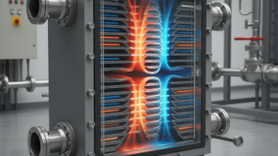
Calculate the log mean temperature difference, or LMTD, using counterflow temperatures: LMTD = (ΔT1 − ΔT2) / ln(ΔT1 / ΔT2). For example, hot fluid entering at 80°C and leaving at 60°C transfers heat to cold fluid rising from 50°C to 55°C. The terminal differences are 30°C and 5°C, producing an LMTD of about 13.7°C. The 5°C outlet approach fits the target range, but fouling may reduce real performance. Field conditions are rarely perfect.
The ASHRAE Handbook—Fundamentals and TEMA Standards recommend checking flow arrangement, correction factors, fouling resistance, and allowable pressure drop. Crossflow or multipass designs require an LMTD correction factor. Ignoring it can oversize or undersize the exchanger. The IEA’s Energy Efficiency 2023 report estimates that industry consumes about 37% of global final energy, so even modest heat-recovery gains deserve careful engineering. A neat spreadsheet can still mislead. Verify fluid properties at operating temperatures, not catalogue conditions. Ensure the selected unit maintains the approach during startup, turndown, and seasonal changes.
Keep Allowable Pressure Drop Within the Typical 20–70 kPa Range
How to Choose the Right Inside Heat Exchanger?
Keep Allowable Pressure Drop Within the Typical 20–70 kPa Range
When selecting an inside heat exchanger, treat pressure drop as a design limit, not a vague preference. A practical target is usually 20–70 kPa at the specified operating flow. This range can support useful turbulence without consuming excessive pump head. Check the exchanger-side pressure drop separately from piping, valves, filters, and fittings. Otherwise, a healthy exchanger may appear restrictive.
Request performance data at the actual fluid temperature, flow rate, density, and viscosity. Water data can mislead when glycol, oil, or process liquids are involved. Review both circuits, because the hot side and cold side rarely share identical conditions. Then compare total pressure loss with available pump head and control requirements. Leave room for fouling, but do not hide poor sizing behind a large safety margin.
In practical commissioning, record inlet and outlet pressures with calibrated gauges. Take readings after air is removed and flow has stabilized. A 35 kPa estimate may become 55 kPa in service. That difference matters near the pump curve. A clean calculation can still mislead. Fouling, partly closed valves, and inaccurate flow measurements often explain the gap. Do not select the smallest exchanger only because its purchase price looks attractive. It may transfer heat well while creating an unacceptable operating burden. Recheck minimum, normal, and peak flow conditions before approving the selection.